
Switch Mode Power Supply Circuit Diagram


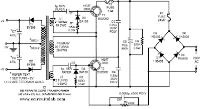
The SMPS described here is suit-able for high-wattage stereos and other similar equipment. The circuit employs two high-voltage power transistors (BU208D) which have built-in re-verse-connected di-odes across their collectors and emitters. It can supply about 250-watt out-put. The circuit uses a ferrite core transformer of 14mm width, 20mm height, and 42mm length of E-E cores. An air gap of 0.5 mm is required between E-E junction. Good insulation using plastic-insulating sheets (Mylar) is to be maintained between each layer of winding.

 Switch Mode Power Supply Circuit Diagram
 Switch Mode Power Supply Circuit Diagram

The number of primary turns required is 90 with 26 SWG wire. The secondary winding employs 17 SWG wire (for 4A load current). Each turn of the secondary develops approximately 2 volts. The reader can decide about the output volt-age and the corresponding secondary turns, which would work out to be half the desired secondary voltage. The volt-age rating of capacitors C7 and C8 should be at least twice the secondary output of each secondary section. BY396 rectifier diodes shown on the secondary side can be used for a maximum load current of 3 amperes.

Two feedback windings (L1 and L2) using two turns each of 19 SWG wire are wound on the same core. These windings are connected to transistors T1 and T2 with a phase difference of 180o,  as shown by the polarity dots in the figure. First wind the primary winding (90 turns using 26 SWG wire) on the former. Then wind the two feedback windings over the secondary (output). Ensure that each winding is separated by an insulation layer.  Two separate heat sinks are to be pro-vided for the two transistors (BU208D).

The filter capacitor for mains should be of at least 47µF, 350V rating. It is better to use a 100µF, 350V capacitor. If the output is short-circuited by less than 8-ohm load, the SMPS would automatically turn off because of the absence of base current.  The hfe min (current amplification factor) of BU208D is 2.5. Thus, sufficien base current is required for fully satu rated operation, otherwise the transistors get over-heated. At times, due to use of very high value of capacitors C7 and C8 (say 2200mF or so) on the secondary side or due to low load, the oscillations may cease on the primary side. This can be rectified by increasing the value of capacitor C6 to 0.01mF.

Author :  Deepu P.A

Comments

Popular posts from this blog

3 Channels Audio Splitter Amplifier Circuit Diagram using TL084

This is the schematic diagram of 3 channels audio splitter amplifier circuit which built using op-amp IC TL084. The 3 channels amplifier output distribution applies a single TL084.   3 Channels Audio Splitter Amplifier Circuit Diagram The very first step is to capacitive coupling having a p. 1.0 ~ electrolytic capacitor. The entries are railways Vee Y2 or 4.5 V. This enables working with an individual 9V power source. A voltage gain of 10 (1 M?/100 Kohm) is obtained in the first stage, as well as the other three floors are connected as a unity gain voltage followers. Every single output stage drives independently through an amplifier output 50 pF capacitor towards the resistance of 5.1 k ohm load. The response range is flat from 10 Hz to 30 kHz.

Simple Automatic Street Light

There have been lot of problems in street lights. Major problem in some places is every evening a person has to come and switch ON the street light and it should be again switched off in morning. Yes, this may not be the situation in everywhere but exists in many places. So this problem can be overcome by using a simple circuit. Below shown circuit will be automatically switched ON and OFF during night and morning times respectively. Circuit diagram : Simple Automatic street light Circuit Diagram In above circuit R1 can be used to adjust the sensitivity. And the working of the circuit is very simple. The LDR will have very low resistance during day time so the transistor Q1 will be in OFF condition. And during night time the resistance will be very high so automatically the transistor Q1 will be ON. The Q1 is PNP transistor and the emitter of Q1 is given to base of Q2. So the Q2 transistor will be ON only if the transistor Q1 is ON. The TRIAC is used in the circuit to make is circ...

Apples Next iPhone to Arrive Sept 10

Apple will unveil the next edition of the iPhone at a major press event on Sept. 10, according to All Things D.Other than the purported date for the unveiling of the so-called iPhone 6, the site's Ina Fried did not offer any details about what else we might expect from Apple with the arrival of the company's first new smartphone since the debut of the iPhone 5 last September. If Apple does lift the curtain on its next-generation iPhone on Sept. 10, it would be two days short of a full year since the iPhone 5 was revealed. While Apple CEO Tim Cook is rumored to be under pressure from Apple's board to step up the pace of innovation and product release schedules, that lag between new iPhone releases wouldn't be particularly unusual for the company—Apple went 16 months between introducing the iPhone 4 and iPhone 4S , for example. But as Fried noted, even as Apple has continued to enjoy robust sales of the iPhone this year, the company has seen its overall share of the gl...