
Steps AVR Programming a Best Chip


This is a complete AVR Tutorial, including avr programming in a very basic & organized way, We will go through by following items.
  • What is an AVR?
  • Using Mac and Windows
  • How AVR programming works
  • Choosing a programmer, to burn the code.
  • Using AVRDUDE
Click Here is one for Windows

What is a micro-controller?

The best way to explain what a microcontroller is, is to start with your computer. Your desktop computer (or laptop) is comprised of multiple parts, a CPU (such as a Pentium or Celeron), some RAM, a hard disk, a keyboard and mouse and a monitor screen. Programs are stored on the hard disk and run on the CPU, with temporary data stored in RAM. You can run multiple programs at a time by having one ‘master program’ called an operating system (such as Linux, Windows or Mac OS X) and that master program keeps track of things for you.

AVR Programming Chip
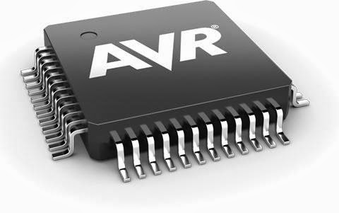

AVR Programming

The AVR chip has components, too. It has a CPU, some flash storage, some RAM and some EEPROM, all in one little chip!. The CPU is just like the one in a computer, but its much simpler and not nearly as fast (what do you expect for $2.50?) The flash storage is just like the flash storage in your mp3 player or digital camera card, except its used to store programs. Its kinda like the hard disk of the microcontroller, except you can only read from it. The RAM is just like computer RAM. The EEPROM is kinda like flash except you cant run a program from it, but its used as long term storage. The EEPROM doesnt get erased when the chip loses power.

So, to recap: The AVR chip runs whatever program is stored in the flash, uses the RAM for temporary storage and the EEPROM for longer term storage.

Most computers have a 32-bit CPU running at 1GHz, with 1GB of RAM and 100 GB of storage. The kinds of micro-controllers discussed here run at 10MHz, have 1KB of RAM and 10KB of storage. (On the order of) However, their small size, lower power consumption and low cost make them an excellent choice for many projects!


Comments

Popular posts from this blog

3 Channels Audio Splitter Amplifier Circuit Diagram using TL084

This is the schematic diagram of 3 channels audio splitter amplifier circuit which built using op-amp IC TL084. The 3 channels amplifier output distribution applies a single TL084.   3 Channels Audio Splitter Amplifier Circuit Diagram The very first step is to capacitive coupling having a p. 1.0 ~ electrolytic capacitor. The entries are railways Vee Y2 or 4.5 V. This enables working with an individual 9V power source. A voltage gain of 10 (1 M?/100 Kohm) is obtained in the first stage, as well as the other three floors are connected as a unity gain voltage followers. Every single output stage drives independently through an amplifier output 50 pF capacitor towards the resistance of 5.1 k ohm load. The response range is flat from 10 Hz to 30 kHz.

Simple But Automatic Load Sensing Power Switch

This circuit will automatically switch on several mains-powered "slave" loads when a "master" load is turned on. For example, it will switch on the amplifier and CD player in a stereo system when the receiver is turned on. It works by sensing the current draw of the "master" device through a low value high wattage resistor using a comparator. The output of that comparator then switches on the "slave" relay. The circuit can be built into a power bar, extension cord or power center to provide a convenient set of "smart" outlets that switch on when the master appliance is powered (turn on the computer monitor and the computer, printer and other peripherals come on as well). Automatic Load Sensing Power Switch Circuit Diagram Parts List: Notes: This circuit is designed for 120V operation. For 240V operation, resistors R2 and R6 will need to be changed. A maximum of 5A can be used as the master unless the wattage of R1 is increased S1 provid...

RF amplifier protection

RF amplifier protection I have developed the protection circuit for the EB104 amplifier I am working on, after I finally had some time to design and test a few models. The main requirements have been: - protection in case of high temperature; - protection in case of high SWR; - protection in case of wrong output filter selection; - simple design (i’m a fan of the whole K.I.S.S. rule of thought), able to work in strong electromagnetic fields, reliable, inexpensive. Because i will be using the same directional coupler i have used in the SWR meter (the one made on PCB) wich is directly influenced by the signal frequency, and because i want full HF coverage, i cannot just measure the reflected signal and make a circuit cut the amplifier when it goes over a limit; on 28Mhz the coupler generates roughly 4 times more voltage that let’s say in 7Mhz. So a system that compares direct and reflected signal and triggers when the latter is percentually too high was needed, therefore an operational a...