Digital control system applications


Digital Control System is a branch of the control system with continuous time processes in the region associated with the digital controller as the controller of the control elements that control systems and computing discrete time. Depending on requirements, a digital controller can be shaped microcontroller and ASIC to a standard desktop computer. Because the digital computer system is discrete, then the Laplace transform is used in the control system is replaced with the Z-transform. Therefore, you must understand about the concept of continuous time and discrete time concept.
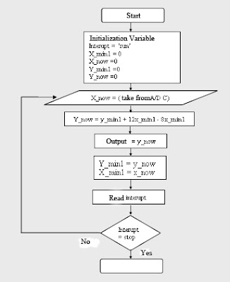

Digital Control system applications
Flow Chart - Digital Control system applications

Digital computer also has a limited precision (See quantization) extra care needed to ensure that errors in the coefficients, A / D conversion, D / A conversion, etc. do not produce unwanted effects or planned.

The application of digital control can easily be done when used in a feedback form. Since the creation of the first digital computer in the early 1940s the price of digital computers has dropped significantly. The reason this is one of the many reasons for the application of digital control systems for the control of the control system. Other reasons:

Flexibile: easy to configure and reconfigure through software
* Scalable: can be set up programs tailored to the limits of memory or storage space at no extra cost
* Adaptable: program parameters can be changed with the times
* Static operation: digital computers are much more susceptible to environmental conditions rather than of capacitors and inductors

Comments

Popular posts from this blog

Build a 3000W Stereo Power Amplifier Circuit Diagram

How to Build a 3000W Stereo Power Amplifier Circuit Diagram? Lets start first we define 3000wstereo power amplifier circuit diagram this circuit has a power output of up to 1500W RMS power amplifier circuit is often used to power sound systems spelunker for outdor. In the final image can be seen a series of power amplifiers using 10 sets of power transistors for the ending. This power amplifier circuit using a transistor amplifier from the front, signal splitter, driver and power amplifier. Current consumption required is quite large power amplifier that is 15-20 A 1500W power amplifier circuits for this. Supply voltage needed by the power of this amplifier is the optimal working order symmetrical 130VDC (130VDC-130VDC ground). 1500W amplifier circuit below is a picture series of mono, stereo if you want to make it necessary to make two copies of the circuit. For more details can be viewed directly image the following 1500W power amplifier circuit. The series of High Power Amplifier 15...

Build a Key Operated Gate Locking System Circuit

This simple key-operated gate locking system allows only those persons who know the preset code to open the gate. The code is to be entered from the keypad within the preset time to operate the motor fitted in the gate. If anyone trying to open the gate presses a wrong key in the keypad, the system is disabled and, at the same time, sounds an alarm to alert you of an unauthorized entry. Figs 1 and 2 show the block and circuit diagrams of the key-operated code locking system, respectively. Connect points A, B, C, D, E, F and ground of the circuit to the respective points of the keypad. Keys S7, S16, S14 and S3 are used here for code entry, and the remaining keys are used for disabling the system. It is very important to press the keys in that order to form the code. To start the motor of the gate, press switches S7, S16, S14 and S3 sequentially. If the keys are pressed in a different order from the preset order, the system will lock automatically and the motor will not start. Fig. 1: Bl...

3 Channels Audio Splitter Amplifier Circuit Diagram using TL084

This is the schematic diagram of 3 channels audio splitter amplifier circuit which built using op-amp IC TL084. The 3 channels amplifier output distribution applies a single TL084.   3 Channels Audio Splitter Amplifier Circuit Diagram The very first step is to capacitive coupling having a p. 1.0 ~ electrolytic capacitor. The entries are railways Vee Y2 or 4.5 V. This enables working with an individual 9V power source. A voltage gain of 10 (1 M?/100 Kohm) is obtained in the first stage, as well as the other three floors are connected as a unity gain voltage followers. Every single output stage drives independently through an amplifier output 50 pF capacitor towards the resistance of 5.1 k ohm load. The response range is flat from 10 Hz to 30 kHz.