The BVM1 is an ultra low power ten LED battery voltmeter circuit that is optimized for monitoring solar-charged 12V battery systems. The circuit features an expanded meter scale that displays ten color-coded voltage steps from 10.5V to 15.0V. Power is conserved by only turning on the appropriate LED for a short but bright flash once every 1.25 seconds. The LED display can be turned on continuously (no blinking) by turning the Calibrate switch on, more battery power is consumed in this mode.
BVM1-12 Volt Battery Voltage Monitor With Parts List
The BVM1 also includes a battery low voltage beeper that warns when the battery voltage drops below a preset voltage. The beeper can be turned on and off with the L.V. Beep Activate switch.
The BVM1 is protected against reverse voltage connection and is fused for safety.
The design goals of this circuit were efficiency, simplicity, reliability and the use of field replaceable parts. The BVM1 circuit has been designed to work in conjunction with both the SCC3 Solar Charge Controller and the SPC3 Solar Power Center. Both devices are also available as kits from CirKits.com.
Specifications
Supply voltage: 12VDC (nominal)
Display voltage range: 10.5V-15V in .5V steps
Maximum input voltage: 17.5VDC
Supply Current @ 12.5V (beep off): 6.25 mA average, 30mA peak.
Supply Current @ 12.5V (beep on): 7 mA average, 34mA peak.
Blink/Beep rate: 1.25 seconds per flash.
Blink/Beep duty cycle: 80% off, 20% on.
Beep frequency: 2.6 Khz.
L.V. Beep threshold adjustment range: 7.5V-13.5V.
Theory
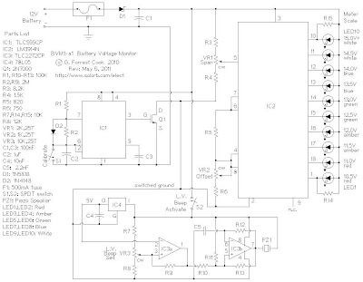
12VDC power is supplied to the BVM1 circuit via a two pin screw connector, it is routed to the rest of the circuit through fuse F1. Diode D1 protects the circuit from the application of reverse battery polarity on the input. Capacitor C1 filters out high frequency noise from the power input.
With the Calibrate switch off, timer IC1 produces a low duty cycle pulse on it's output, pin 3. If the Calibrate switch is turned on, the IC1 output stays on. The output signal is sent to MOSFET Q1, which turns the negative-side power bus of the IC2 voltmeter and the beep circuit on and off.
The LM3914N voltmeter, IC2, is wired as an expanded scale voltmeter with a nominal voltage display from 10.5 to 15.0V in .5V steps. All of the LEDs will turn off below 10.5V and the 15.0V LED will stay on at 15.0V and above. Potentiometer VR1 adjusts the voltage span covered by IC2 and potentiometer VR2 adjusts the voltage point where each LED turns on. Resistor R5 sets the LED current to around 20mA.
The low voltage beeper circuit is activated by turning on S2, the L.V. Beep Activate switch. IC4 provides a steady 5V reference. IC3a is wired as a comparator circuit with hysteresis. IC3a compares the 5V reference to the battery voltage, which is scaled to a value near 5V by R7, VR3 and R8. When the scaled battery voltage falls below the reference voltage, the output of IC3a goes low and turns on IC3b, a 3Khz square wave oscillator. IC3b drives the piezo speaker, PZ1. On low battery voltages, the beep sounds when the LED blinks, or constantly if the Calibrate switch is on. Turning the L.V. Beep Activate switch always shuts off the beeper.
Use
Connect the BVM1 input connections to the battery terminals. Turn the Calibrate switch S1 OFF and the LED array will blink to indicate the battery voltage. Turn the Calibrate switch S1 ON and the LED array will remain on, this mode will consume slightly more battery current. The calibrate mode is useful for displaying quickly fluctuating DC voltages. All of the LEDs will turn off if the input voltage is below 10.5V and the white LED will stay on for all voltages above 15V.
Turn the Beep On switch S2 ON (toward the center of the board) to enable the low battery voltage beeper. To disable the beep, turn the Beep On switch to the OFF position.
BVM1-12 Volt Battery Voltage Monitor With Parts List
The BVM1 also includes a battery low voltage beeper that warns when the battery voltage drops below a preset voltage. The beeper can be turned on and off with the L.V. Beep Activate switch.
The BVM1 is protected against reverse voltage connection and is fused for safety.
The design goals of this circuit were efficiency, simplicity, reliability and the use of field replaceable parts. The BVM1 circuit has been designed to work in conjunction with both the SCC3 Solar Charge Controller and the SPC3 Solar Power Center. Both devices are also available as kits from CirKits.com.
Specifications
Supply voltage: 12VDC (nominal)
Display voltage range: 10.5V-15V in .5V steps
Maximum input voltage: 17.5VDC
Supply Current @ 12.5V (beep off): 6.25 mA average, 30mA peak.
Supply Current @ 12.5V (beep on): 7 mA average, 34mA peak.
Blink/Beep rate: 1.25 seconds per flash.
Blink/Beep duty cycle: 80% off, 20% on.
Beep frequency: 2.6 Khz.
L.V. Beep threshold adjustment range: 7.5V-13.5V.
Theory
12VDC power is supplied to the BVM1 circuit via a two pin screw connector, it is routed to the rest of the circuit through fuse F1. Diode D1 protects the circuit from the application of reverse battery polarity on the input. Capacitor C1 filters out high frequency noise from the power input.
With the Calibrate switch off, timer IC1 produces a low duty cycle pulse on it's output, pin 3. If the Calibrate switch is turned on, the IC1 output stays on. The output signal is sent to MOSFET Q1, which turns the negative-side power bus of the IC2 voltmeter and the beep circuit on and off.
The LM3914N voltmeter, IC2, is wired as an expanded scale voltmeter with a nominal voltage display from 10.5 to 15.0V in .5V steps. All of the LEDs will turn off below 10.5V and the 15.0V LED will stay on at 15.0V and above. Potentiometer VR1 adjusts the voltage span covered by IC2 and potentiometer VR2 adjusts the voltage point where each LED turns on. Resistor R5 sets the LED current to around 20mA.
The low voltage beeper circuit is activated by turning on S2, the L.V. Beep Activate switch. IC4 provides a steady 5V reference. IC3a is wired as a comparator circuit with hysteresis. IC3a compares the 5V reference to the battery voltage, which is scaled to a value near 5V by R7, VR3 and R8. When the scaled battery voltage falls below the reference voltage, the output of IC3a goes low and turns on IC3b, a 3Khz square wave oscillator. IC3b drives the piezo speaker, PZ1. On low battery voltages, the beep sounds when the LED blinks, or constantly if the Calibrate switch is on. Turning the L.V. Beep Activate switch always shuts off the beeper.
Use
Connect the BVM1 input connections to the battery terminals. Turn the Calibrate switch S1 OFF and the LED array will blink to indicate the battery voltage. Turn the Calibrate switch S1 ON and the LED array will remain on, this mode will consume slightly more battery current. The calibrate mode is useful for displaying quickly fluctuating DC voltages. All of the LEDs will turn off if the input voltage is below 10.5V and the white LED will stay on for all voltages above 15V.
Turn the Beep On switch S2 ON (toward the center of the board) to enable the low battery voltage beeper. To disable the beep, turn the Beep On switch to the OFF position.
(C) 2011, G. Forrest Cook
Comments
Post a Comment