
Transformerless Power Supply


Description:
This circuit will supply up to about 20ma at 12 volts. It uses capacitive reactance instead of resistance; and it doesn't generate very much heat.The circuit draws about 30ma AC.If you need more current, use a larger value capacitor; or put two in parallel; but be careful of what you are doing to the Watts. 

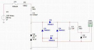
The low voltage 'AC' is supplied by D1 and D8.Also you can replace R3 and D3 with a 78 Series regulator.


Schematic:
  

Components:
  u1,   100ma fuse
   R1,   100 ohm ,  0.25watt
   R2,   1K ohm,   2 watt
   R3,   1k ohm ,  0.25watt
   C1,   470nF,  400v, polyseter
   D4-D7,   1N4001 or 1N4007
   D1, D8,   16v Zener Diode
   C2,   1uF  electrolyte
   D2,   12v Zener Diode 

Comments

Popular posts from this blog

Build a 3000W Stereo Power Amplifier Circuit Diagram

How to Build a 3000W Stereo Power Amplifier Circuit Diagram? Lets start first we define 3000wstereo power amplifier circuit diagram this circuit has a power output of up to 1500W RMS power amplifier circuit is often used to power sound systems spelunker for outdor. In the final image can be seen a series of power amplifiers using 10 sets of power transistors for the ending. This power amplifier circuit using a transistor amplifier from the front, signal splitter, driver and power amplifier. Current consumption required is quite large power amplifier that is 15-20 A 1500W power amplifier circuits for this. Supply voltage needed by the power of this amplifier is the optimal working order symmetrical 130VDC (130VDC-130VDC ground). 1500W amplifier circuit below is a picture series of mono, stereo if you want to make it necessary to make two copies of the circuit. For more details can be viewed directly image the following 1500W power amplifier circuit. The series of High Power Amplifier 15...

3 Channels Audio Splitter Amplifier Circuit Diagram using TL084

This is the schematic diagram of 3 channels audio splitter amplifier circuit which built using op-amp IC TL084. The 3 channels amplifier output distribution applies a single TL084.   3 Channels Audio Splitter Amplifier Circuit Diagram The very first step is to capacitive coupling having a p. 1.0 ~ electrolytic capacitor. The entries are railways Vee Y2 or 4.5 V. This enables working with an individual 9V power source. A voltage gain of 10 (1 M?/100 Kohm) is obtained in the first stage, as well as the other three floors are connected as a unity gain voltage followers. Every single output stage drives independently through an amplifier output 50 pF capacitor towards the resistance of 5.1 k ohm load. The response range is flat from 10 Hz to 30 kHz.

Amplifier Circuit 2 X 10 watt with IC AN7145

This is Stereo Amplifier On this schematic amplifier circuit  use the ic AN7145L , but can use the following IC : AN7145M AN7145H AN7146M AN7146H You can use of all ic above. anthis circuit need suply voltage with dual voltage . Minimum voltage 6 Volt and maximum voltage 20 volt . Voltage just (-) and (+), but (-) can also ground. Maximum power output 2 X 20 watt with minimum impedance 4 ohm. Click image to view enlarge. You can operate this circuit with  plugging input to , PC or other media can give signal audio.