
Hofner Colorama II restoration project part 8 painting the guitar body


In the last blog post, we lacquered the neck on our vintage Hofner Colorama II guitar. Today we will paint the body.

Before painting, we do a last check for anything we may have missed, like scrapes or gouges in the wood. This leads us to discover that the raw plug/screw anchor that someone had inserted to hold on the rear strap button, and which we were just going to leave, is, in fact, just half a raw plug.


So, out it comes:


A new hole is drilled:


A wooden plug is cut:


Glued in:


And filed/sanded flat:
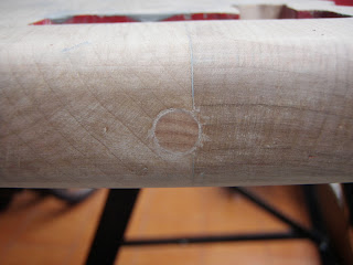


Finally, we drill a new strap button hole:


Et voilà.


Also, since we're at it, let's drill a hole from the control cavity through to the tremolo area, so that we can earth (ground) the tremolo unit when we put this thing back together:


Now on with the show. A quick mounting system needs to be fabricated, so we cut a piece of wood that can be attached to the neck pocket. We drill a hole in it too, so that we can hang it up. We’ll also put a screw in the rear strap button hole to give us another contact point to move the guitar body around while we’re spraying it.


We give the guitar body a quick wipe down to remove any dust, etc:


Now here’s the body hanging up in our specially-designed spray booth (the spare bathroom, which, btw, has very good ventilation). We make sure to wear suitable eye and mouth/nose protection before proceeding:
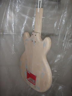


And so the spraying begins. We're just using standard car (auto touch-up) paint spray cans for this:


Here’s the body after a layer or two. As you can see, the body filler is showing through. However the original paint job had no primer/undercoat, and we want to keep it that way, so we will keep applying layers until the filler is no longer visible:


After a few more layers there is no sign of the filler:


Here’s the guitar body after two cans of spray paint. We’ll hang it up to dry for a week or two and then sand it with very fine sandpaper. If necessary, some additional layers of paint will be applied. After that, it will receive some lacquer (which will be shown in later posts):


Comments

Popular posts from this blog

3 Channels Audio Splitter Amplifier Circuit Diagram using TL084

This is the schematic diagram of 3 channels audio splitter amplifier circuit which built using op-amp IC TL084. The 3 channels amplifier output distribution applies a single TL084.   3 Channels Audio Splitter Amplifier Circuit Diagram The very first step is to capacitive coupling having a p. 1.0 ~ electrolytic capacitor. The entries are railways Vee Y2 or 4.5 V. This enables working with an individual 9V power source. A voltage gain of 10 (1 M?/100 Kohm) is obtained in the first stage, as well as the other three floors are connected as a unity gain voltage followers. Every single output stage drives independently through an amplifier output 50 pF capacitor towards the resistance of 5.1 k ohm load. The response range is flat from 10 Hz to 30 kHz.

Simple But Automatic Load Sensing Power Switch

This circuit will automatically switch on several mains-powered "slave" loads when a "master" load is turned on. For example, it will switch on the amplifier and CD player in a stereo system when the receiver is turned on. It works by sensing the current draw of the "master" device through a low value high wattage resistor using a comparator. The output of that comparator then switches on the "slave" relay. The circuit can be built into a power bar, extension cord or power center to provide a convenient set of "smart" outlets that switch on when the master appliance is powered (turn on the computer monitor and the computer, printer and other peripherals come on as well). Automatic Load Sensing Power Switch Circuit Diagram Parts List: Notes: This circuit is designed for 120V operation. For 240V operation, resistors R2 and R6 will need to be changed. A maximum of 5A can be used as the master unless the wattage of R1 is increased S1 provid...

RF amplifier protection

RF amplifier protection I have developed the protection circuit for the EB104 amplifier I am working on, after I finally had some time to design and test a few models. The main requirements have been: - protection in case of high temperature; - protection in case of high SWR; - protection in case of wrong output filter selection; - simple design (i’m a fan of the whole K.I.S.S. rule of thought), able to work in strong electromagnetic fields, reliable, inexpensive. Because i will be using the same directional coupler i have used in the SWR meter (the one made on PCB) wich is directly influenced by the signal frequency, and because i want full HF coverage, i cannot just measure the reflected signal and make a circuit cut the amplifier when it goes over a limit; on 28Mhz the coupler generates roughly 4 times more voltage that let’s say in 7Mhz. So a system that compares direct and reflected signal and triggers when the latter is percentually too high was needed, therefore an operational a...