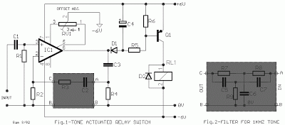
This is a simple project of Relay Switch Activated by Tone and Signal circuit diagram.The essence of the circuit is for the input of tone and signal to provide an activation for the relay switch.
- Relay – an electrically operated switch where the current flowing through the coil of the relay is creating a magnetic field which attracts a lever and changes the switch contacts, thereby making its state open or close
- BC214 – a complementary silicon planar epitaxial transistor used in AF small signal drivers and am1 as well as for low noise preamplifier applications due to its feature of good linearity of DC current gain
- LM741 – a general purpose single operational amplifier with features such as offset null, compensated internal freq uency, voltage range with high input, good stability of temperature, and protected from short circuit
The use of relay will allow the circuit to switch from one condition to another. It can also be referred to as a form of an electrical amplifier since it is able to control an output circuit of higher power than the input circuit. There are many types of relays being used in many electronic and electrical circuits, which include solid-state relay, Buchholz relay, overload protection relay, latching relay, forced-guided contacts relay, mercury-wetted relay, contactor relay, machine tool relay, reed relay, polarized relay, and solid state contactor relay.

The circuit created is sensitive enough to the AC signals in the input stage, where the signals are ranging above 5 mV. It will also be sensitive to react with the human voice signals having a range of frequency from 50 Hz up to 3 KHz. The human voice is a part of the human sound produced primarily by the vocal cords or vocal folds which in turn produces a voice frequency that is used for the transmission of speech.
During the absence of an input signal, the state of the 12 V relay RL1 is at OFF condition as regulated by the 10K Ohms trimmer RV1. The circuit can be made to react with its sensitivity in points A, B, & C, where a negative feedback can be placed due to the addition of band pass filter. The filter will operate only in the 1 KHz range and the circuit will only correspond at this frequency.
During the absence of an input signal, the state of the 12 V relay RL1 is at OFF condition as regulated by the 10K Ohms trimmer RV1. The circuit can be made to react with its sensitivity in points A, B, & C, where a negative feedback can be placed due to the addition of band pass filter. The filter will operate only in the 1 KHz range and the circuit will only correspond at this frequency.

The signal and tone activated relay switch were used in a wide range of fields which includes measuring instruments, audio systems, communications equipment, and factory-automation equipment. They can also be found on telephone subscriber circuits for the polarity reversing switch, testing, and ringing functions. Source
Comments
Post a Comment