Rechargeable batteries of 6V and 12V are used in a large number of applications. It is imperative that these are maintained properly to get maximum life out of them. Further, their permissible number of charge-discharge cycles must be fully utilised. Here is a circuit that gives a visual as well as an audible alarm if the battery voltage is higher or lower than acceptable limits, so that corrective action can be taken.

Circuit and working
As shown in Fig. 1, the circuit is built around dual-operational amplifier LM358 (IC1), hex inverting Schmitt trigger 74HC14 (IC2) and a few other components. The circuit can be divided into two parts—the input unit built around two operational amplifiers (op amps) in IC1 working as comparators, and audio alarm unit built around two RC oscillators and a transistor.

Voltage from the battery under test (BUT) is applied to connector CON1. It is divided by five by R1 and R2 for comparison with the threshold levels. the power supply of the circuit is limited to 5V ±2%. SPDT switches S1 and S2 simultaneously select between the preset threshold for 6V and 12V rechargeable batteries. potentiometers VR1 and VR2 set the highest allowable input voltage. For example, for a 12V battery, if you wish to activate the visual and audio alarms at 14.5V, you should set the potentiometer VR2 reference voltage to 14.5V/5 = 2.9V.
Potentiometers VR3 and VR4 set the lowest allowable input voltage. For example, for a 12V battery, if you wish to activate the visual and audio alarms at 10.8V, you should set the potentiometer VR4 reference voltage to 10.8V/5 = 2.16V. Similarly, you can obtain the reference voltages for a 6V battery by setting potentiometers VR1 and VR3.
When the input voltage is above the threshold set by potentiometers VR1 or VR2, the output at pin OUT1 of IC1 becomes low and the LED2 indicating a high voltage switches on. The output of gate N1 of IC2 becomes high and the RC oscillator built around gate N2 oscillates. The output, which is a square wave with frequency of approximately 1kHz, is amplified by gate N3 and transistor T1 and reproduced by the headphone loudspeaker (LS1) or an earphone. The frequency of the RC oscillator built around gate N2 can be set with the help of resistor R7 and capacitor C2 to an appropriate value.
When the input voltage is below the threshold set by VR3 or VR4, the output at pin OUT2 of IC1 becomes high. The output of gate N4 becomes low and the LED3 indicating a low voltage switches on. The RC oscillator built around gate N5 starts working. The produced square wave signal with frequency of around 1kHz is amplified by gate N6 and transistor T1 and reproduced by the headphone loudspeaker (LS1) or an earphone. The frequency of the RC oscillator built around gate N5 can be set with resistor R8 and capacitor C3 to an appropriate value.


When the input signal is within the range set by the selected potentiometers, both the oscillators do not work, and there is no sound from the loudspeaker and the LEDs LED2 and LED3 remain off.
Power supply for the circuit may be derived from 78L/M/05 (not shown) with 5V and ±2 per cent tolerance and connected at CON2. LED1 is the power indicator.
Construction and testing
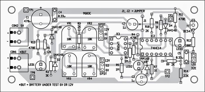
An actual-size, single-side PCB for the voltage monitor for 6V/12V batteries is shown in Fig. 2 and its component layout in Fig. 3. After assembling the circuit on a PCB, enclose it in a suitable plastic box.
Fix CON1 on the front side of the case for connecting the battery under test (BUT). Fix CON2 on the rear side of the box for connecting a 5V power supply to the circuit.
Before use, check that voltages at the test points are as per the table.
Circuit and working
As shown in Fig. 1, the circuit is built around dual-operational amplifier LM358 (IC1), hex inverting Schmitt trigger 74HC14 (IC2) and a few other components. The circuit can be divided into two parts—the input unit built around two operational amplifiers (op amps) in IC1 working as comparators, and audio alarm unit built around two RC oscillators and a transistor.
Voltage from the battery under test (BUT) is applied to connector CON1. It is divided by five by R1 and R2 for comparison with the threshold levels. the power supply of the circuit is limited to 5V ±2%. SPDT switches S1 and S2 simultaneously select between the preset threshold for 6V and 12V rechargeable batteries. potentiometers VR1 and VR2 set the highest allowable input voltage. For example, for a 12V battery, if you wish to activate the visual and audio alarms at 14.5V, you should set the potentiometer VR2 reference voltage to 14.5V/5 = 2.9V.
Potentiometers VR3 and VR4 set the lowest allowable input voltage. For example, for a 12V battery, if you wish to activate the visual and audio alarms at 10.8V, you should set the potentiometer VR4 reference voltage to 10.8V/5 = 2.16V. Similarly, you can obtain the reference voltages for a 6V battery by setting potentiometers VR1 and VR3.
When the input voltage is above the threshold set by potentiometers VR1 or VR2, the output at pin OUT1 of IC1 becomes low and the LED2 indicating a high voltage switches on. The output of gate N1 of IC2 becomes high and the RC oscillator built around gate N2 oscillates. The output, which is a square wave with frequency of approximately 1kHz, is amplified by gate N3 and transistor T1 and reproduced by the headphone loudspeaker (LS1) or an earphone. The frequency of the RC oscillator built around gate N2 can be set with the help of resistor R7 and capacitor C2 to an appropriate value.
When the input voltage is below the threshold set by VR3 or VR4, the output at pin OUT2 of IC1 becomes high. The output of gate N4 becomes low and the LED3 indicating a low voltage switches on. The RC oscillator built around gate N5 starts working. The produced square wave signal with frequency of around 1kHz is amplified by gate N6 and transistor T1 and reproduced by the headphone loudspeaker (LS1) or an earphone. The frequency of the RC oscillator built around gate N5 can be set with resistor R8 and capacitor C3 to an appropriate value.
Fig. 1: Circuit diagram of monitor for 6V/12V batteries
Fig. 2: Actual-size PCB layout for the monitor circuit
Fig. 3: Component layout for the PCB
When the input signal is within the range set by the selected potentiometers, both the oscillators do not work, and there is no sound from the loudspeaker and the LEDs LED2 and LED3 remain off.
Power supply for the circuit may be derived from 78L/M/05 (not shown) with 5V and ±2 per cent tolerance and connected at CON2. LED1 is the power indicator.
Construction and testing
An actual-size, single-side PCB for the voltage monitor for 6V/12V batteries is shown in Fig. 2 and its component layout in Fig. 3. After assembling the circuit on a PCB, enclose it in a suitable plastic box.
Fix CON1 on the front side of the case for connecting the battery under test (BUT). Fix CON2 on the rear side of the box for connecting a 5V power supply to the circuit.
Before use, check that voltages at the test points are as per the table.
Sourced BY: EFY Author Name: Petre Tzv Petrov
Comments
Post a Comment