RF amplifier protection
I have developed the protection circuit for the EB104 amplifier I am working on, after I finally had some time to design and test a few models. The main requirements have been:
- protection in case of high temperature;
- protection in case of high SWR;
- protection in case of wrong output filter selection;
- simple design (i’m a fan of the whole K.I.S.S. rule of thought), able to work in strong electromagnetic fields, reliable, inexpensive.
Because i will be using the same directional coupler i have used in the SWR meter (the one made on PCB) wich is directly influenced by the signal frequency, and because i want full HF coverage, i cannot just measure the reflected signal and make a circuit cut the amplifier when it goes over a limit; on 28Mhz the coupler generates roughly 4 times more voltage that let’s say in 7Mhz. So a system that compares direct and reflected signal and triggers when the latter is percentually too high was needed, therefore an operational amplifier was the natural choice. This will solve the SWR problem, and because the directional coupler will sit between the amplifier output and the low-pass filters, it will also trigger when a wrong band is selected.
The thermal problem will be even more easy to fix, i will use a NTC thermistor in a resistive divider; the second operational amplifier from the LM358 IC I have chosen to use will just compare the voltage from the resistive divider to a preset one, and will trigger when the thermistor’s value gets too small.
As usual, it’s much easier to understand when pictured:
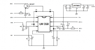
C1 – 100uF / 16V
C2 – 470uF / 6.3V
C3 … C10 – 10nF ceramic
R1, R4 – 470 ohm
R2 – 1 Kohm
R3 – 10 Kohm
VR1, VR2 – 10 Kohm
D1 … D4 – 1N4148
The circuit will trigger once one of the two described conditions will take place, and will remain like this until power is removed for 10 seconds, due to D1 or D4 diodes. A LED connected between LED1 + and LED1 – points will signal SWR protection enabled, and a LED connected between LED2+ and LED2 – will signal thermal protection enabled. TH+ and TH- will be connected to a 1Kohm NTC thermistor wich will be placed on the heatsink, as close to the amplifier’s power transistors as possible, and the FWD and REF points will be connected to a SWR sensing board like the one described in the SWR meter article. For reliable operation, low-pass filters on both FWD and REF lines might be needed, made from a series 1Kohm resistor and a 10 uF / 16V capacitor to ground.
There are many ways in wich the amplifier might be stopped from working once these protections trigger. Switching back the RX/TX relay while in full operation might be dangerous (for a second both transmitter and amplifier will work without a load) plus the relay might be damaged. The simple way is to cut down the power of the amplifier by removing the gate bias, by simply connecting the BC107′s collector (BIAS point) to the bias voltage regulator’s reference circuit (pin 5 of MC1723CP in the Eb104 schematic). This will still allow you to remain on the air, the transmitter will see the correct impedance on the amplifier’s input and the amplifier’s finals will be able to handle even infinite SWR and the heatsink will get the chance to cool down due to running in low power mode. SSB or AM work will be a problem, because the amplifier will work in C class now.
This has been tested with 100W on both antenna and dummy load, it’s working OK, the real test will be when the rest is finished though.
source:link
Comments
Post a Comment